
 info@cn-wh.cn


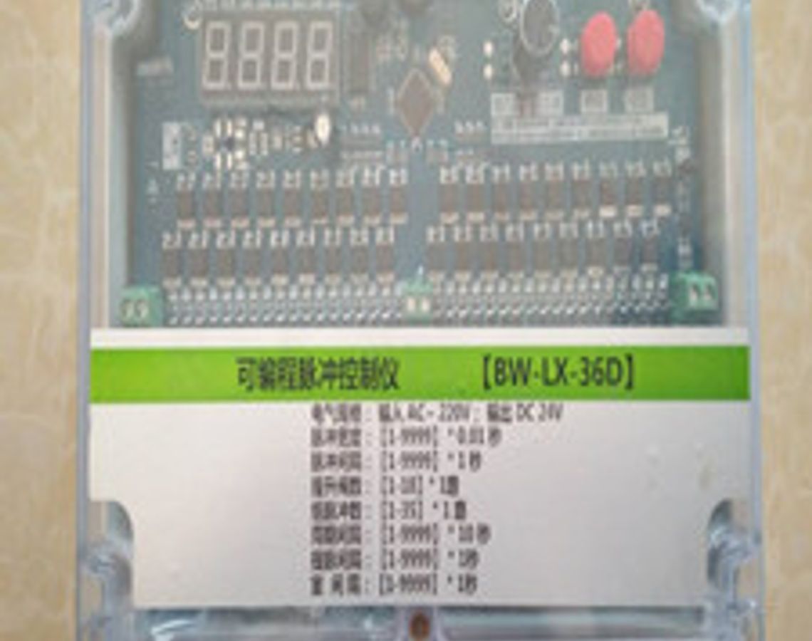


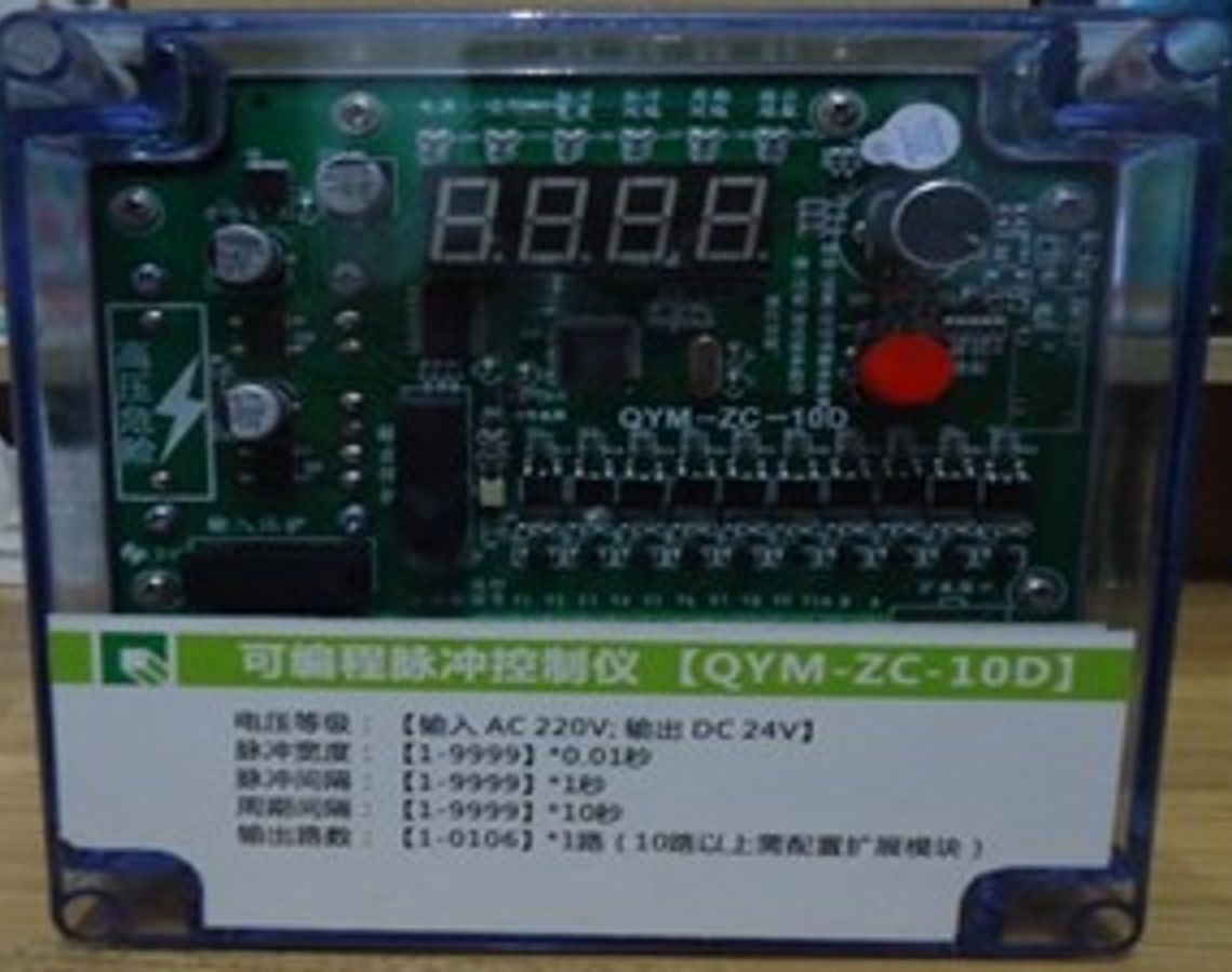
BW-LX-36D programmable offline pulse controller
The offline pulse controller adopts a common hardware + control algorithm design scheme, which excellently solves the contradiction between reducing control costs and improving control reliability. By choosing this controller, users only need to install peripheral equipment correctly and set parameters correctly to easily realize electrical control of the dust collector without any programming.
1. Product features
The offline pulse controller uses an industrial-grade microcontroller as the control core;
The offline pulse controller adopts an advanced bus display method, which not only displays the normal working status of the equipment, but also facilitates the setting of working parameters;
The offline pulse controller panel is equipped with working instructions for each output point, which can quickly determine the status of the output point;
The offline pulse controller adopts a universal hardware + control algorithm design scheme, which excellently solves the contradiction between reducing control costs and improving control reliability. By choosing this controller, users only need to install peripheral equipment correctly and set parameters correctly to easily realize electrical control of the dust collector without any programming;
The controller adopts EEPROM data storage technology to realize control parameters can be modified at any time and saved during power failure. Since the control parameters of the system have special protection measures, the safety of the control parameters can still be maintained even in particularly harsh environments.
2. Technical indicators
Number of output channels: 1-40 channels optional;
The control parameters can be set at any time, and the set parameters will not be lost after power failure;
Support remote start/stop control (optional);
Input voltage: AC 50HZ 180-240V;
Each output voltage: DC 24V;
Output current of each channel: DC 1.0A;
It can realize online (sequential pulse) and offline (boost + pulse) control;
Support ash discharge control;
Overall dimensions: 260×185×96 mm
3. Parameter setting range
Pulse raising interval: The setting range is 05~99 seconds, and the system default value is 5 seconds;
Pulse width: The setting range is 1~999 seconds, the system default is 10 seconds;
Valve interval: The setting range is 003~999 seconds, and the system default is 003 seconds;
Period interval: The setting range is 001~9990 seconds, and the system default is 10 seconds;
Dust removal time: The setting range is 0~99 seconds, and the system default is 05 seconds;
Ash discharge interval: The setting range is 0~99 seconds, and the system default is 50 seconds;
Number of poppet valves: the number of chambers, the setting range is 0~10, the system default is 00;
Set to 0 when there is no poppet valve;
Number of pulse valves: The setting range is 01~36, and the system default is 36;
Interventricular interval: The setting range is 01-99 seconds, the system default is 05;
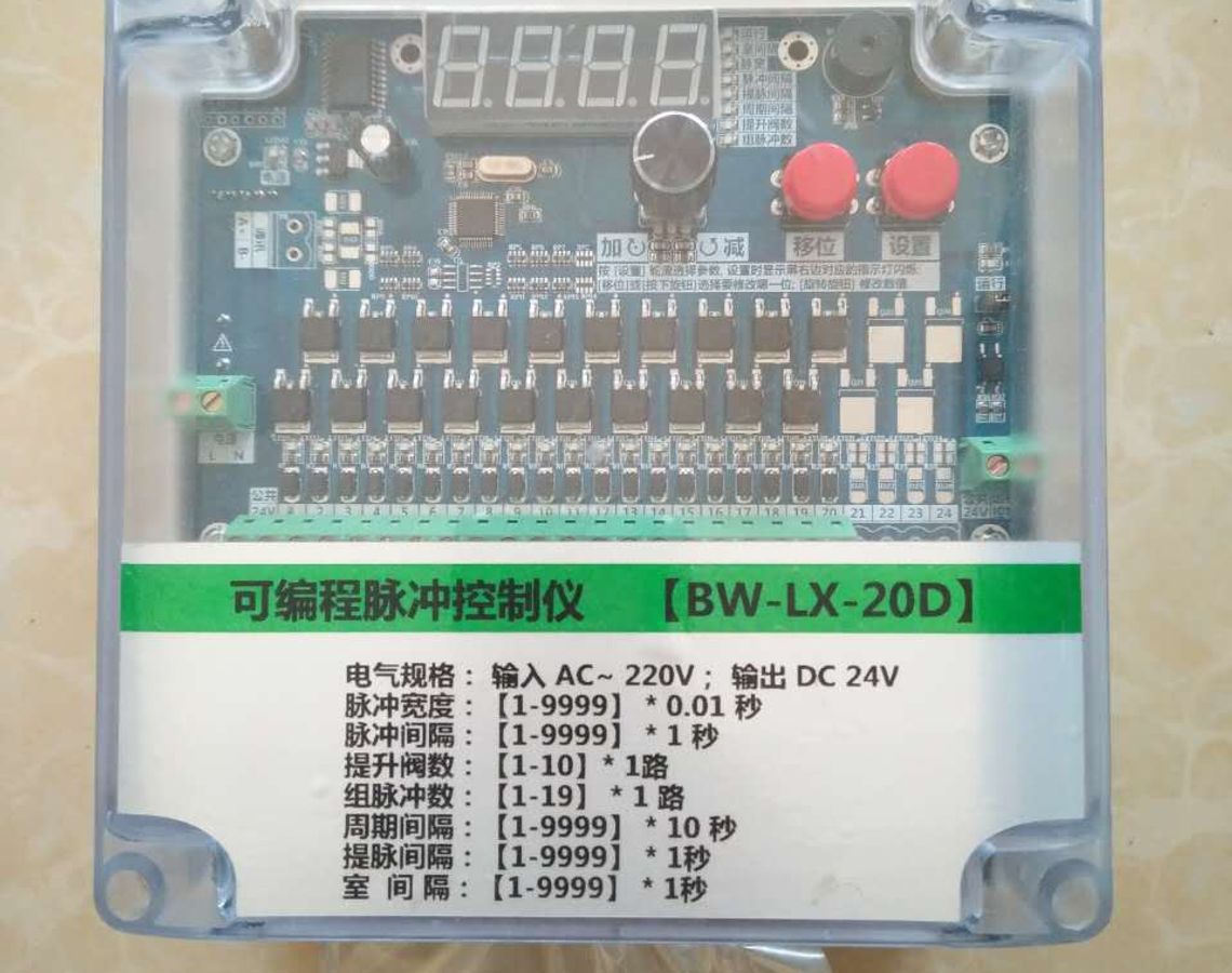
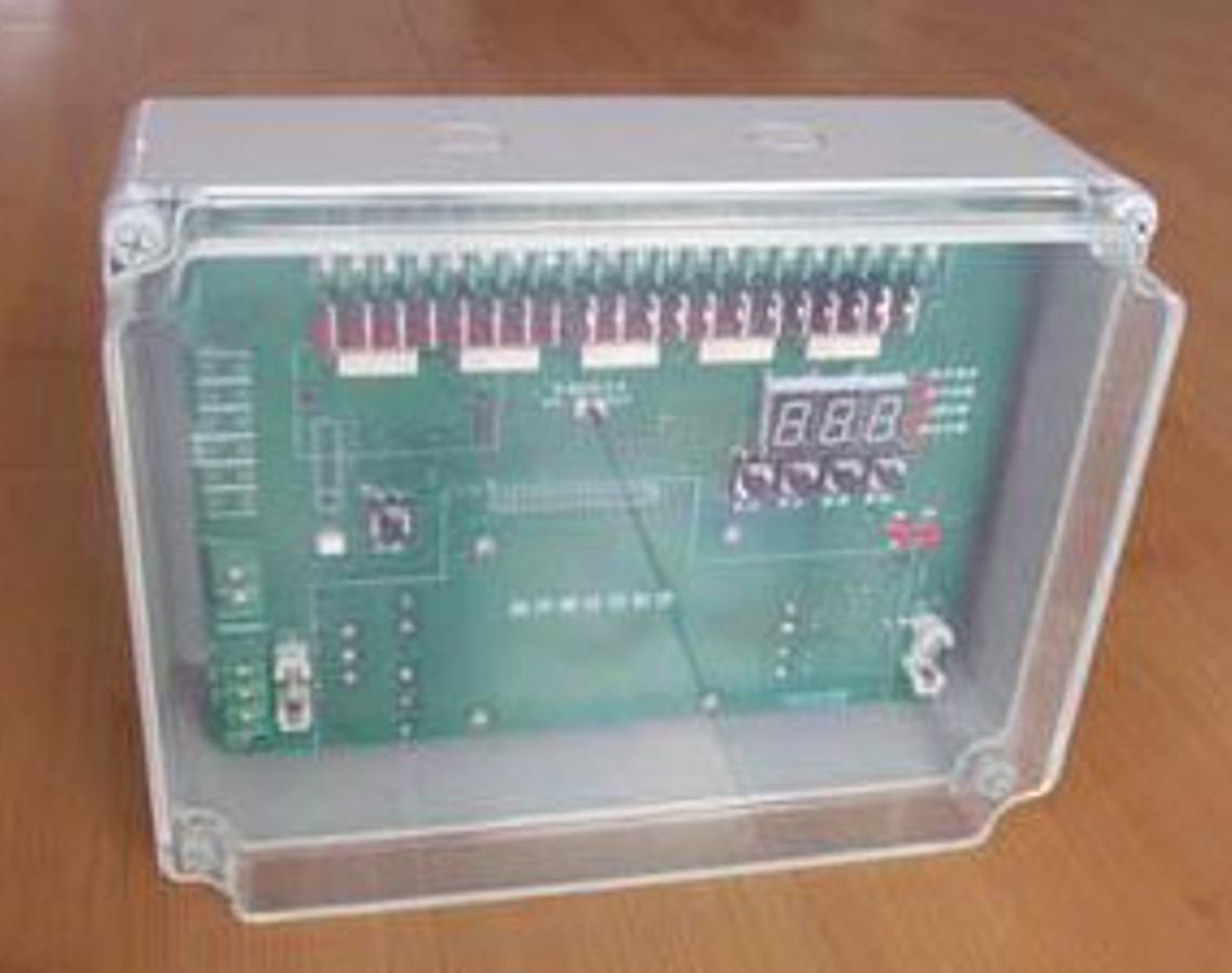
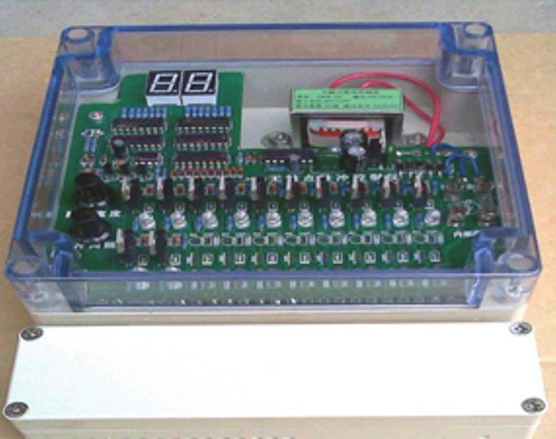
4. Panel instructions:
The functions of each part of the panel:
1) Digital tube: operation display, setting parameters and operation process parameter display;
2) Up key (red): Add button;
3) Middle button (yellow): Set/shift button;
4) Down button (red): manual button;
5) Indicator lights 1-40: Indicate the working status of each output point;
6) For the terminal arrangement diagram, see Part 6 - Wiring Method.
5. Wiring method: (TMY-FD-BD terminal diagram)
Wiring instructions:
1) 1~2 are AC 220V input terminals (L, N);
2) 3~4 is the common terminal DC24- for the valve;
3) 5~44 are pulse valve signal output terminals;
4) The polarity of the outlet terminals of terminals 5-44 is DC24+, and this machine provides 2 common terminals;
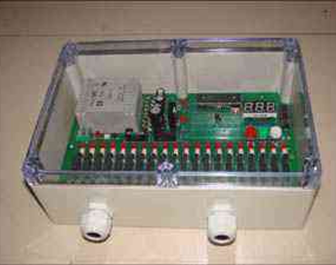
6. Installation method:
Because the T pulse controller adopts a waterproof transparent plastic casing, it effectively isolates the impact of external dust on the control chip and can be installed in places with high dust concentrations.
7. Operation instructions:
After the controller meets the startup conditions, the controller will perform dust cleaning operations on each room in sequence. After each room has completed one dust cleaning operation, it will be judged whether the dust unloading conditions are met. If the dust unloading conditions are met, start unloading dust. If not, the cycle interval delay will be entered. The length of the delay is determined by the "cycle interval". When the cycle interval delay ends, a new round of dust cleaning operation begins.
Parameter setting and modification:
The TMY-FD controller automatically controls according to the set parameters without any operation after power on. , the controller has five main states - standby state, running state, power-on self-test state, manual inspection state, and control parameter modification state.
In the control state, if the power-saving mode of the controller is 1, the digital tube displays the countdown to the next output "pulse", and the output status of each output point can be monitored online with the output instructions above the terminals on the lower side of the controller. If the controller's display mode is 0, the controller's display will be the same as mode 1 within 30 seconds after starting or stopping key operations. Once it exceeds 30 seconds, only the third decimal point of the display flashes once per second and enters the power saving mode.
Running state: The controller enters the power-on operating state after meeting the power-on conditions. The digital tube displays the countdown of time, and the light-emitting diodes display the status of each output point.
Manual inspection state: When the controller is running normally, press the "Increase" button, and the system will enter the manual inspection state. At this time, press the "Manual" button, and the output will shift backward from ground to ground until the "Add" button is pressed again. Press the "Add" key to exit the manual state.
Parameter modification status: At any time, press the "Set" button for more than 0.5 seconds and then release it, the controller will enter the control parameter modification mode. The TMY-FD series controller has 10 control parameters including pulse raising interval, valve interval time, output pulse width, number of lift valves, number of group pulse valves, cycle interval, power saving mode, ash unloading time and ash unloading interval. Modify Each digital tube always displays the number of the modified parameter. The modification sequence, meaning and display format during modification are as follows:
1. "Pulse lifting interval time" - is the time interval between the output of the poppet valve and the operation of the pulse valve of this unit, the unit is seconds. According to the process requirements, the pulse raising interval time can be set at any time according to the on-site working conditions, and its value is between 5 and 99 seconds.
2. "Pulse width" - the duration of the output pulse, its adjustment range is 0.02 to 0.99 seconds. When setting, the unit is 0.01 second, so the setting value is from 0.02 to 0.99.
3. "Valve interval time" - is the time interval from the end of a certain valve output pulse to the start of the adjacent valve output pulse, the unit is seconds. According to process requirements, the pulse interval time can be set at any time according to on-site working conditions, and its value is between 3 and 999 seconds.
4. "Cycle interval" - the time interval between two adjacent cleaning cycles, in seconds. Its adjustment range is 1 to 9990S.
5. "Duration of ash discharge" - the action time of the ash discharge valve. The adjustment range of this parameter is 0-99S.
6. "ash discharge interval" - the number of dust cleaning cycles between two adjacent dust discharge valve action times. The adjustment range of this parameter is 0-99 times.
7. "Number of poppet valves" - when this parameter is set to 0, it is in the online dust cleaning state, when it is non-0, it is in the offline working state, and its adjustment range is 0-9.
8. "Number of pulse valves in group" - the number of pulse valves controlled by each poppet valve. When modifying, the 3rd to 4th digits from the left of the display display the tens and ones digits of each group of pulse valves respectively. The adjustment range is 1-18. The setting of this parameter is limited by the number of output channels and needs to be set after calculation.
9. "Display mode"--the working mode of the monitor. 0 is economic mode, 1 is normal mode. The display modes are explained in more detail at the beginning of this chapter.
A. "Chamber interval" - when the number of poppet valves is not 0, the time interval from when the last pulse valve of the previous unit is powered off to when the poppet valve of the lower unit is activated. The adjustment range of this parameter is 0-99 times.
Press the "Set" button to enter the parameter modification mode. There is always and only one digit "flashing" on the display, and this number is the current modification object. Press the "increase" button for more than 0.5 seconds and then release it, the "flash" number will increase by 1. If the number after adding 1 exceeds the number allowed by the bit, the "flashing" number will change to the small number allowed by the bit. Once the "flashing" number is the required number, press and release the "Set" button again for more than 0.5 seconds, and the next digit on the display will "flash". If the current "flashing" is the next number of a certain control parameter, the display will display the next control parameter and its number will "flash". If the current "flashing" number is the last number of the last control parameter, the parameter modification mode ends, the controller automatically saves all control parameters and immediately uses the control parameters to implement control. Once the control parameters are saved, they will be saved until the next modification operation.
If there is no operation within 20 seconds after entering the modification mode, the controller will automatically abandon the current modification results and return to the control state.
If you find that the data of the previous digit is incorrect after entering the modification state of the next digit, you can continue to press/release the "Set" button, and the controller will automatically increase the digit label → exit the modification state → modify again.
Notice:
1. The control parameters can be saved only after modifying the last number of the last control parameter.
2. Since the working voltage on the circuit board and wiring terminals is as high as 220V, your hands must be kept dry during operation and do not touch the wiring terminals and circuit boards. Otherwise, electric shock may occur.
3. Since the "Settings", "Add" and "Manual" buttons are plastic miniature buttons, you should press them vertically and lightly during operation. Do not press too hard or at an angle, otherwise the buttons will be easily damaged.
9. After-sales service:
Free guidance on installation and debugging. We will train electronic control professionals for the user unit; if there is any problem with the user’s normal use within 6 months after the sale, our company will be responsible for free repairs; lifetime warranty, if the repair exceeds 6 months or occurs due to abnormal use, the maintenance cost and transportation will be charged. , postage fee; free replacement of control program, transportation and postage fees are charged; upgrade and product customization services are provided, customization service fee is charged;
Notice:
Since the working voltage on the circuit board and wiring terminals is as high as 220V, your hands must be kept dry during operation and do not touch the wiring terminals and circuit boards. Otherwise, it may cause an electric shock accident; there should be no corrosive gas around the controller, and try to avoid strong vibrations. , strong magnetism, high temperature and high heat places; in order to ensure normal production and equipment safety, the number of control channels and pulse valves should be adjusted by professional technicians.

Brochure

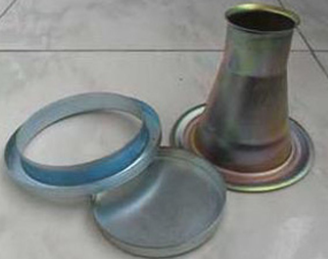
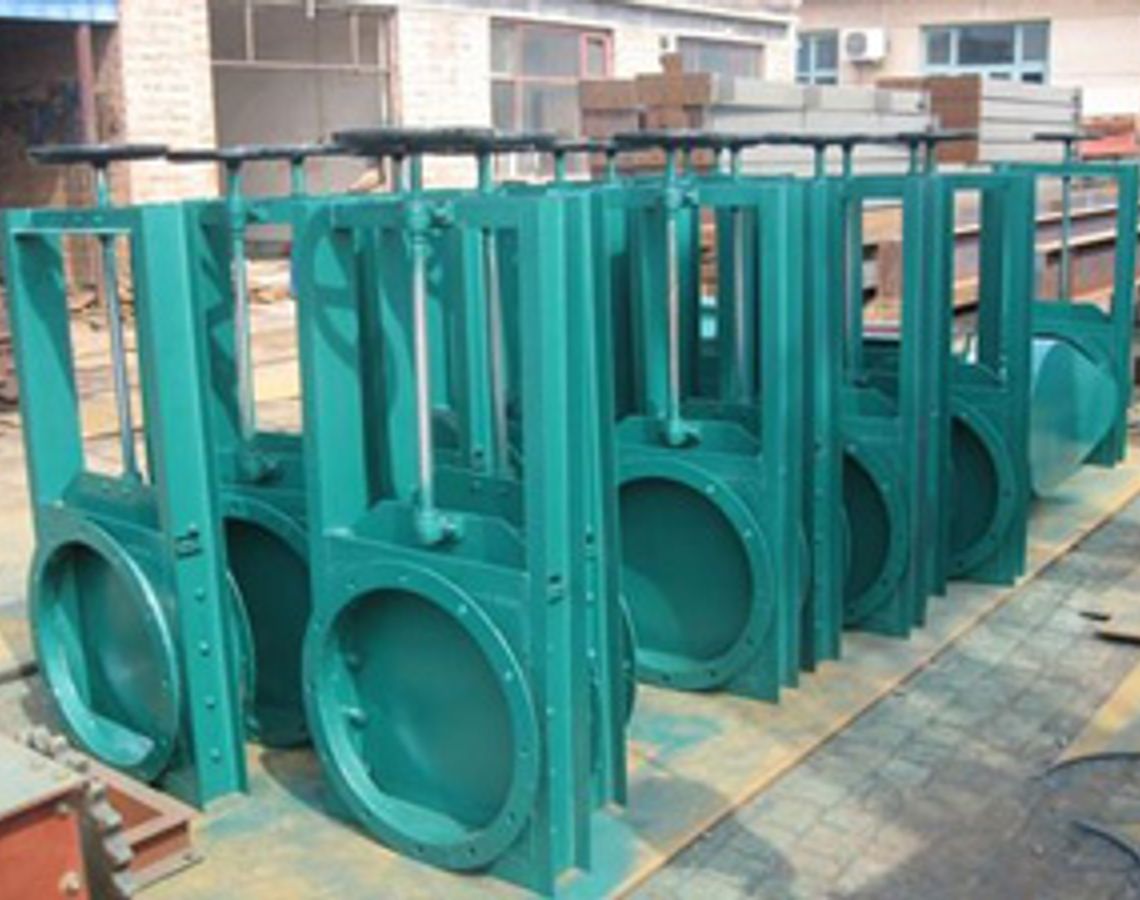
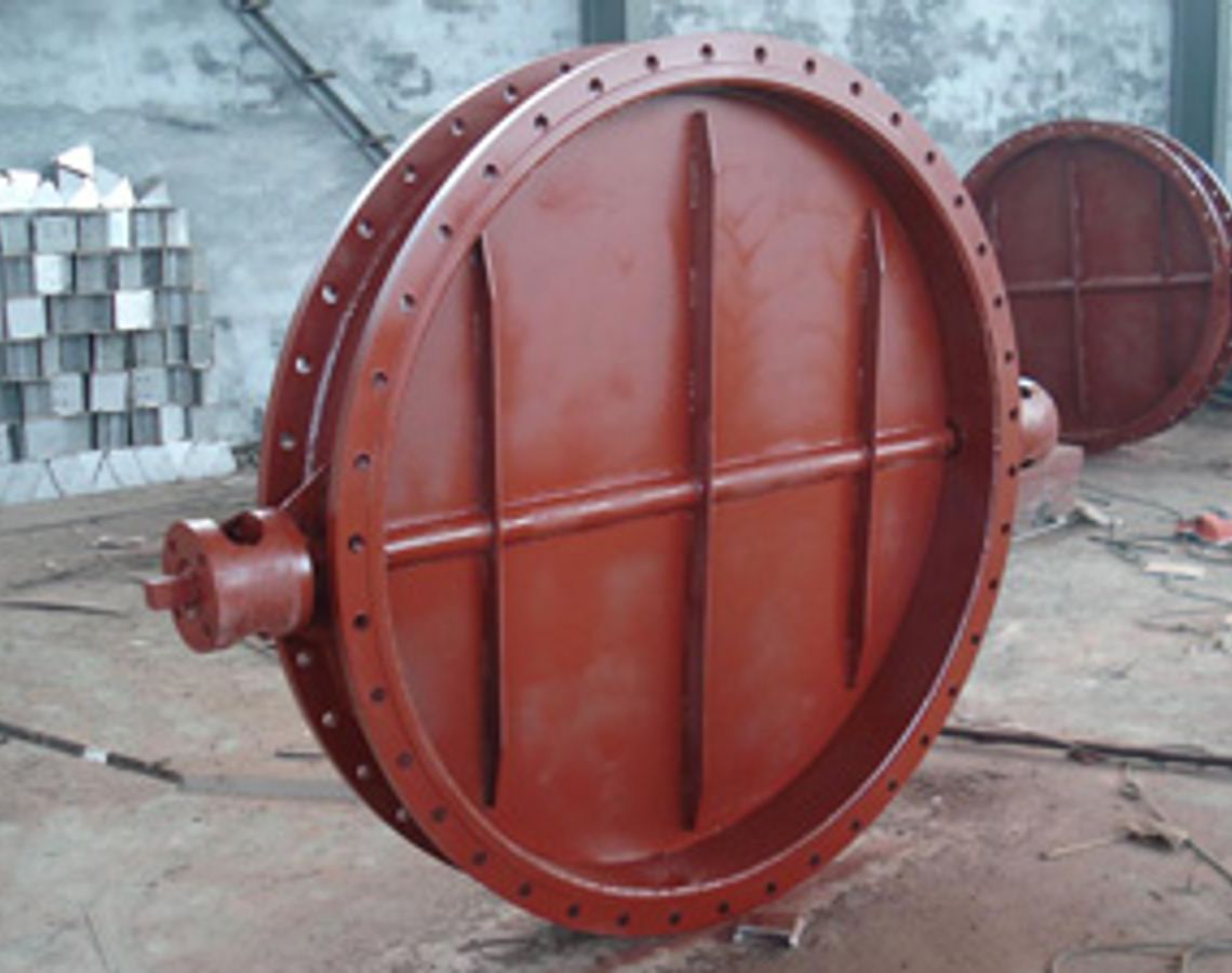
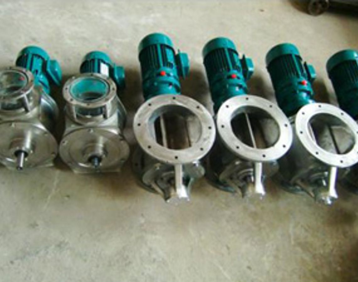
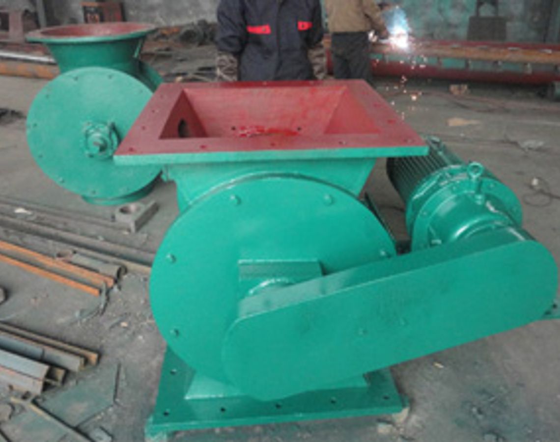
Related Products
Our Advantages

Stable Operation

Convenient Operation

Easy Installation

Fast Dust Removal

Direct Factory Sales

On-Time Delivery

Customization

After-Sales Guarantee

Installation Instructions
Before installing the equipment, ensure that the foundation is level;
When installing bag dust collectors and multi-tube dust collectors, pay attention to leaving empty space for ash unloading;
After installation, thoroughly clean the inside of the dust collector, and no tools or debris are allowed to remain. The manhole must be tightly sealed.


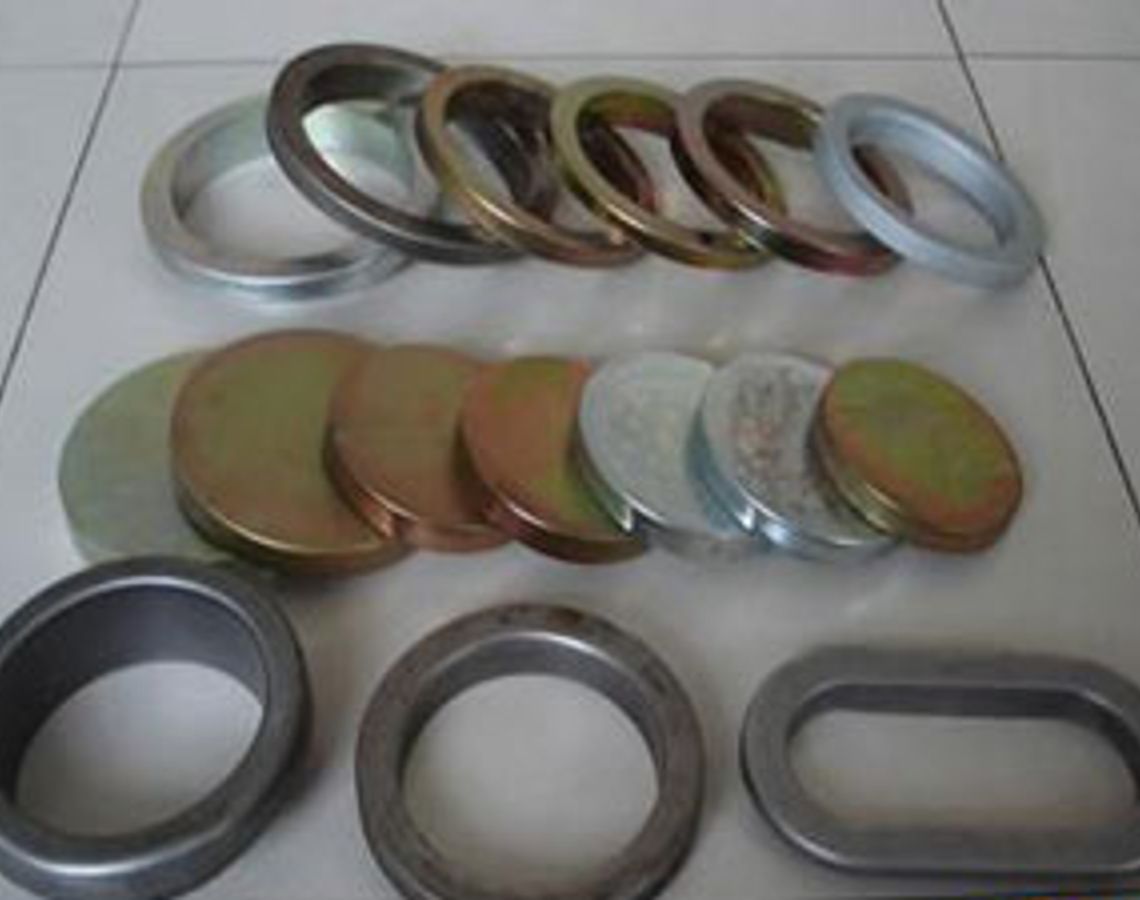
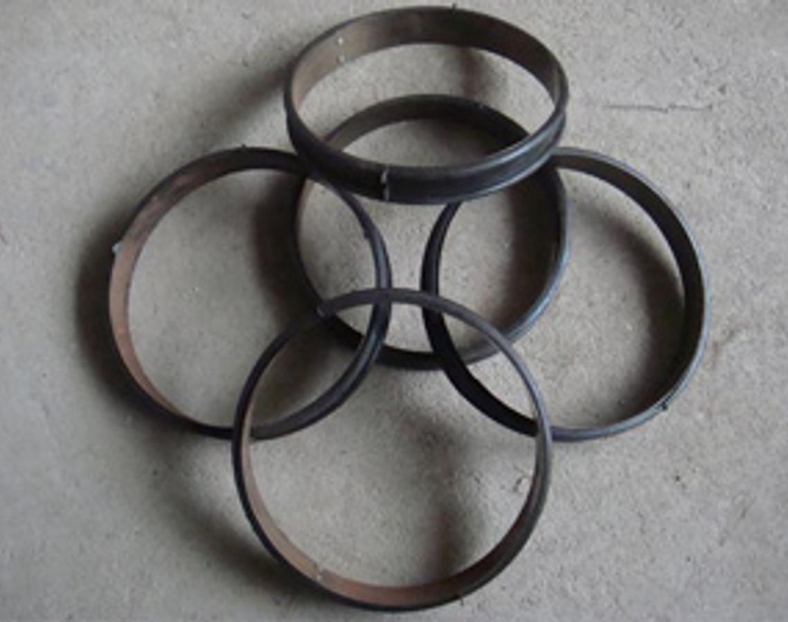
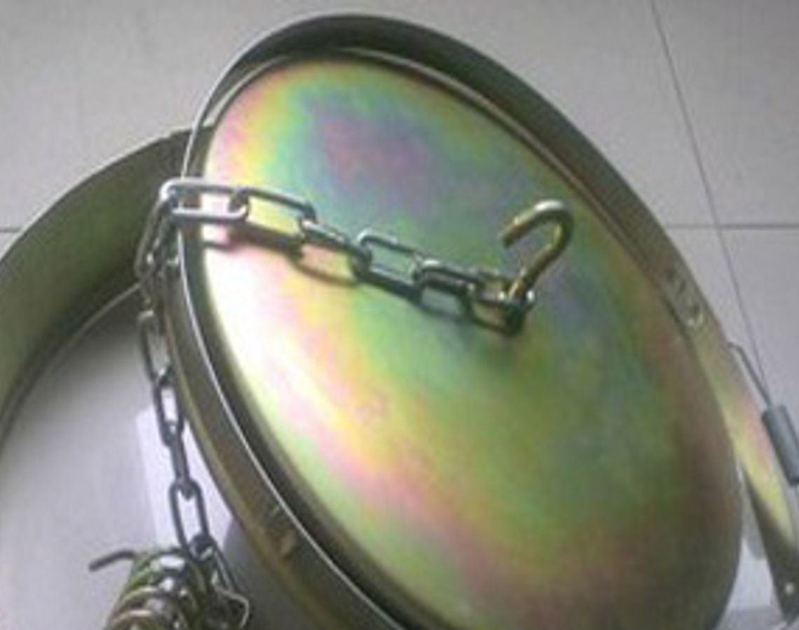
Related Products


Application Industry

Steel Metallurgy

Mining and Mining

Electric Power Industry
Cement Manufacturing

Chemical Industry
Contact
You can contact us in the following four ways. We will communicate with you as soon as we receive your inquiry!
1. Call Us.
2. Send Email.
3. Message Form.
4. Add WeChat or WhatsApp.